
 United Kingdom
 Australia
 France
 Germany
 Spain
Spain Netherlands
 Italy
Italy Hungary
Resistance Thermometer - Guide to Platinum Resistance Thermometers
What is a Resistance Thermometer
A resistance thermometer is a temperature sensor which relies on the principle that a metal changes resistance according to its temperature. Not all metals are suited to the demands of accurate and repeatable temperature measurements and in industrial platinum tends to be the standard because it is highly repeatable, stable and produces results that have been standardised. It is also chemically resistant. Copper and Nickel elements are occasionally used, particularly in laboratory or research applications.
How does a Resistance Thermometer Work?
Resistance thermometers incorporate a resistive sensing element mounted insode a stainless steel probe (with associated cable, connector or termianl head). This element is usually a wire wound or thin film platinum element with a resistance of 100 ohms at 0°C. These sensors are commonly referred to as Pt100 sensors. The resistance change as the temperature changes is read by an instrument which passes a small current through the element. This will generate a small voltage and so the resistance can be measured and converted to °F or °C by the instrumentation.

Are Resistance Thermometers Accurate?
Resistance thermometers are extremely accurate sensors. In fact, secondary standards in calibration laboratories are usually resistance thermometers. In industrial use, two factors determine the accuracy of the resistance thermometer:
Tolerance of the element
Under IEC 60751 there are various accuracy bands. Most industrial sensors use a class B element which has an inherent tolerance of ±0.3°C @ 0°C. Class A elements are also widely used which have a tolerance of ±0.15°C @ 0°C. Other elements are available with tolerances of 1/3, 1/5 and 1/10 of class B. Sometimes these are referred to as 1/3 DIN etc.
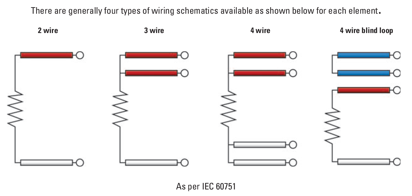
Number of Wires (2 wire, 3 wire and 4 wire)
The resistance element will be connected to cabling which can be configured in either a 2, 3 or 4 wire configuration, depending on the application and instrumentation available.
Because we are measuring resistance it stands to reason that the resistance of the leads (cable) will need to be included in the measurement. In a 2 wire device the lead resistance is added to the resistance of the element. This introduces an error equivalent to the resistance of the leads and this is the least accurate configuration. A 3 wire device effectively compensates for one leg of this lead resistance and a 4 wire resistance thermometer is the most accurate by fully compensating for lead resistance.
Wiring color codes
2-wire Pt100 Sensor = 1 x red wire and 1 white wire
3-wire Pt100 Sensor = 2 x red wires and 1 white wire
4-wire Pt100 Sensor = 2 x red wire and 2 white wires
A color code and wiring diagram is shown below.
For a detailed explanation of wiring and bridge networks for resistance thermometers, please click here.
What are the advantages and disadvantages of Resistance Thermometers?
Resistance thermometers have their own merits for temperature measurement in that they are highly accurate, repeatable and stable, but it has perhaps easier to compare them to thermocouples in order to establish their advantages and disadvantages:
Resistance thermometers have a maximum temperature of 1100°F and more often 480°F, whereas thermocouples can measure up to 2900°F and they generally have slower response time compared to thermocouple. However, resistance thermometers have a much higher accuracy (as mentioned above) are more stable and are less prone to drift.
Resistance thermometers (also known as PRT, RTD sensor, Pt100) are considered more fragile than thermocouples which are rugged sensors that can withstand more mechanical abuse than a resistance thermometer.
RTD Pt100 Resistance Thermometer - Reference Information
Including information on RTD Theory, Resistance Thermometer Materials, RTD Elements, Color Codes, Tolerances and Resistance Vs Temperature Tables

A Typical Industrial Resistance Thermometer
Typical RTD Sensors - Pt100 Resistance Thermometers
Mineral Insulated
Resistance Thermometer
 Our most popular style of resistance thermometer, ideal for most applications. Wide choice of terminations.
Rigid Stem
RTD Temperature Sensor
 Ideal for rigid stem applications or where the sensor is shorter than 2" long, limited to 480°F.
handheld Resistance Thermometers
 A range of handheld RTD Sensors to suit a variety of applications from general purpose to surface and air temperature measurements
Pt100 Sensors for
Surface Measurements
 A wide range of RTD sensors for surface measurements including self adhesive patch, pipe, magnetic etc.
Miniature Pt100
A wide range of RTD sensors for surface measurements including self adhesive patch, pipe, magnetic etc.
Miniature Pt100RTD Sensors
 0.062" and 0.080" diameter sensors ideal for precision fast response measurements or minimal displacement is required
Other Popular Resistance Thermometers
 A wide range of RTD Sensors to suit many applications. Bayonet, bolt, stator slot, basic element styles etc.
Reduced Tip
A wide range of RTD Sensors to suit many applications. Bayonet, bolt, stator slot, basic element styles etc.
Reduced TipRTD Sensors
 Fast response RTD sensors ideal for industrial and other applications
Autoclave
Fast response RTD sensors ideal for industrial and other applications
AutoclaveRTD Sensors
 RTD sensors designed specifically for the harsh environments in autoclaves
What is the formula for a resistance thermometer?
Rt /R0 = 1 + At + Bt2
(above 0°C this second order approach is more than adequate)
or Rt /R0 = 1 + At + Bt2 + Ct3 (t-100)
(below 0°C, if you are looking for higher accuracy of representation, the third order provides it).
Therefore:
t = (1/α)(Rt - R0)/R0 + δ(t/100)(t/100 -1)
Where: Rt is the thermometer resistance at temperature t; R0 is the thermometer resistance at 0°C; and t is the temperature in °C. A, B and C are constants (coefficients) determined by calibration. In the IEC 60751 industrial RTD standard, A is 3.90802 x 10⁻³; B is -5.802 x 10⁻⁷; and C is -4.2735 x 10⁻¹². Incidentally, since even this three term representation is imperfect, the ITS-90 scale introduces a further reference function with a set of deviation equations for use over the full practical temperature range above 0°C (a 20 term polynomial).
The a coefficient, (R100 - R0)/100 . R0, essentially defines purity and state of anneal of the platinum, and is basically the mean temperature coefficient of resistance between 0 and 100°C (the mean slope of the resistance vs temperature curve in that region).
Meanwhile, δ is the coefficient describing the departure from linearity in the same range. It depends upon the thermal expansion and the density of states curve near the Fermi energy. In fact, both quantities depend upon the purity of the platinum wire. For high purity platinum in a fully annealed state the a coefficient is between 3.925x10⁻³/°C and 3.928x10⁻³/°C.
For commercially produced platinum resistance thermometers, standard tables of resistance versus temperature have been produced based on an R value of 100 ohms at 0°C and a fundamental interval (R100 - R0) of 38.5 ohms (α coefficient of 3.85x10⁻³/°C) using pure platinum doped with another metal (see Part 2, Section 6). The tables are available in IEC 60751, tolerance classes A and B.
